Interference and diffraction
Double-slit interferenceedit
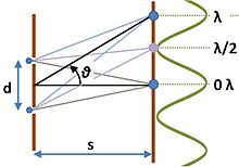
When sinusoidal waveforms add, they may reinforce each other (constructive interference) or cancel each other (destructive interference) depending upon their relative phase. This phenomenon is used in the interferometer. A simple example is an experiment due to Young where light is passed through two slits. As shown in the figure, light is passed through two slits and shines on a screen. The path of the light to a position on the screen is different for the two slits, and depends upon the angle θ the path makes with the screen. If we suppose the screen is far enough from the slits (that is, s is large compared to the slit separation d) then the paths are nearly parallel, and the path difference is simply d sin θ. Accordingly, the condition for constructive interference is:

where m is an integer, and for destructive interference is:

Thus, if the wavelength of the light is known, the slit separation can be determined from the interference pattern or fringes, and vice versa.
For multiple slits, the pattern is

where q is the number of slits, and g is the grating constant. The first factor, I1, is the single-slit result, which modulates the more rapidly varying second factor that depends upon the number of slits and their spacing. In the figure I1 has been set to unity, a very rough approximation.
The effect of interference is to redistribute the light, so the energy contained in the light is not altered, just where it shows up.
Single-slit diffractionedit
The notion of path difference and constructive or destructive interference used above for the double-slit experiment applies as well to the display of a single slit of light intercepted on a screen. The main result of this interference is to spread out the light from the narrow slit into a broader image on the screen. This distribution of wave energy is called diffraction.
Two types of diffraction are distinguished, depending upon the separation between the source and the screen: Fraunhofer diffraction or far-field diffraction at large separations and Fresnel diffraction or near-field diffraction at close separations.
In the analysis of the single slit, the non-zero width of the slit is taken into account, and each point in the aperture is taken as the source of one contribution to the beam of light (Huygens' wavelets). On the screen, the light arriving from each position within the slit has a different path length, albeit possibly a very small difference. Consequently, interference occurs.
In the Fraunhofer diffraction pattern sufficiently far from a single slit, within a small-angle approximation, the intensity spread S is related to position x via a squared sinc function:
- with


where L is the slit width, R is the distance of the pattern (on the screen) from the slit, and λ is the wavelength of light used. The function S has zeros where u is a non-zero integer, where are at x values at a separation proportion to wavelength.
Diffraction-limited resolutionedit
Diffraction is the fundamental limitation on the resolving power of optical instruments, such as telescopes (including radiotelescopes) and microscopes. For a circular aperture, the diffraction-limited image spot is known as an Airy disk; the distance x in the single-slit diffraction formula is replaced by radial distance r and the sine is replaced by 2J1, where J1 is a first order Bessel function.
The resolvable spatial size of objects viewed through a microscope is limited according to the Rayleigh criterion, the radius to the first null of the Airy disk, to a size proportional to the wavelength of the light used, and depending on the numerical aperture:

where the numerical aperture is defined as for θ being the half-angle of the cone of rays accepted by the microscope objective.

The angular size of the central bright portion (radius to first null of the Airy disk) of the image diffracted by a circular aperture, a measure most commonly used for telescopes and cameras, is:

where λ is the wavelength of the waves that are focused for imaging, D the entrance pupil diameter of the imaging system, in the same units, and the angular resolution δ is in radians.
As with other diffraction patterns, the pattern scales in proportion to wavelength, so shorter wavelengths can lead to higher resolution.

Comments
Post a Comment